Application
Note
®
HAL 1820, HAL 24xy,
HAL 28xy, HAL 36xy,
HAL 38xy
Application Board HAL-APB V1.x
Edition Oct. 8, 2012
APN000055_003EN
�HAL1820, HAL24xy, HAL28xy, HAL36xy, HAL38xy
APPLICATION NOTE
Application Board HAL-APB V1.x
Copyright, Warranty,
and Limitation of
Liability
The information and data contained in this document are believed to be accurate and
reliable. The software and proprietary information contained therein may be protected
by copyright, patent, trademark and/or other intellectual property rights of Micronas. All
rights not expressly granted remain reserved by Micronas.
Micronas assumes no liability for errors and gives no warranty representation or guarantee regarding the suitability of its products for any particular purpose due to these
specifications.
By this publication, Micronas does not assume responsibility for patent infringements or
other rights of third parties which may result from its use. Commercial conditions, product availability and delivery are exclusively subject to the respective order confirmation.
Any information and data which may be provided in the document can and do vary in
different applications, and actual performance may vary over time.
All operating parameters must be validated for each customer application by customers’ technical experts. Any new issue of this document invalidates previous issues.
Micronas reserves the right to review this document and to make changes to the document’s content at any time without obligation to notify any person or entity of such revision or changes. For further advice please contact us directly.
Do not use our products in life-supporting systems, military, aviation, or aerospace
applications! Unless explicitly agreed to otherwise in writing between the parties, Micronas’ products are not designed, intended or authorized for use as components in systems intended for surgical implants into the body, or other applications intended to support or sustain life, or for any other application in which the failure of the product could
create a situation where personal injury or death could occur.
No part of this publication may be reproduced, photocopied, stored on a retrieval system or transmitted without the express written consent of Micronas.
Micronas Trademarks
HAL, varioHAL, 1D HAL, 2D HAL, 3D HAL
Third-Party Trademarks
All other brand and product names or company names may be trademarks of their
respective companies.
License Note
HAL36xy and HAL38xy use licenses of Fraunhofer Institute for Integrated Circuits IIS.
2
Oct. 8, 2012; APN000055_003EN
Micronas
�HAL1820, HAL24xy, HAL28xy, HAL36xy, HAL38xy
APPLICATION NOTE
Application Board HAL-APB V1.x
Contents
Page
Section
Title
6
6
6
7
7
8
1.
1.1.
1.2.
1.2.1.
1.2.2.
1.3.
Introduction
General Information
Introduction
Supported HAL Sensors
Sensor-specific PC Software
Board Block Diagram
9
9
9
9
2.
2.1.
2.1.1.
2.1.2.
Getting started
First Steps
Check HAL-APB V1.x
Check Communication with PC and Hall Sensor Connection
10
10
13
13
3.
3.1.
3.2.
3.3.
Board Configuration
Jumper Settings
HAL Interface Connector
Firmware update
14
14
14
15
16
4.
4.1.
4.2.
4.3.
4.4.
Specification
Recommended Operating Conditions
Recommended Wiring
Maintenance and Calibration
Characteristics
17
17
5.
5.1.
USB Driver Installation
Installing the USB VCP Drivers
18
18
18
18
18
19
20
6.
6.1.
6.1.1.
6.1.2.
6.1.3.
6.1.4.
6.1.5.
Board Functions
Serial Command Interpreter
Serial Interface Configuration
Definition of the COMMAND Frame
Definition of the RESPONSE Frame
Analog Measurements
Error Codes
21
21
21
7.
7.1.
7.2.
Board Mode Settings
Board Operation Modes
Board Configuration Commands
Micronas
Oct. 8, 2012; APN000055_003EN
3
�HAL1820, HAL24xy, HAL28xy, HAL36xy, HAL38xy
APPLICATION NOTE
Application Board HAL-APB V1.x
24
24
25
26
27
27
27
27
28
28
28
29
30
8.
8.1.
8.2.
8.3.
8.4.
8.4.1.
8.4.2.
8.4.3.
8.4.4.
8.4.5.
8.4.6.
8.5.
8.6.
HAL 1820
Programming interface
Command Structures of Protocol
Telegram Parameters
Available sensor commands
Read
Write
Protocol Error Handling
Data check
CRC
Parity check
HAL 1820 - Board commands
Locking of the Sensor
31
31
32
33
34
35
35
35
35
35
36
36
37
38
9.
9.1.
9.2.
9.3.
9.4.
9.5.
9.5.1.
9.5.2.
9.5.3.
9.5.4.
9.5.5.
9.5.6.
9.6.
9.7.
HAL24xy
Programming interface
Command Structure of Protocol for communication via VSUP
Command Structure of Protocol for communication via OUT-Pin
Telegram Parameter
Available sensor commands
Set base address
Read
Write
CRC
Parity check
Protocol Error Handling
HAL 24xy - Board commands
Locking of the Sensor
39
39
39
39
40
41
42
10.
10.1.
10.1.1.
10.1.2.
10.1.3.
10.2.
10.3.
HAL 2810 – Board Commands
LIN Interface
LIN Interface Mode Configuration
Schedule Tables
Error Handling
HAL 2810 (LIN2.0) – Board commands
Locking of the Sensor
43
43
44
45
46
46
46
46
47
47
47
47
48
49
11.
11.1.
11.2.
11.3.
11.4.
11.4.1.
11.4.2.
11.4.3.
11.4.4.
11.4.5.
11.4.6.
11.4.7.
11.5.
11.6.
HAL 283x / HAL 2850
Programming interface
Command Structure of Protocol for communication via OUT-Pin
Telegram Parameters
Available sensor commands
Set base address
Read with absolute address
Read with base address
Write byte with base address
Write word with base address
Special Cases
Protocol Error Handling
HAL 283x / HAL 2850 – Board commands
Locking of the Sensor
4
Oct. 8, 2012; APN000055_003EN
Micronas
�APPLICATION NOTE
HAL1820, HAL24xy, HAL28xy, HAL36xy, HAL38xy
Application Board HAL-APB V1.x
50
50
51
52
53
54
55
55
55
55
55
56
56
57
58
12.
12.1.
12.2.
12.3.
12.4.
12.5.
12.6.
12.6.1.
12.6.2.
12.6.3.
12.6.4.
12.6.5.
12.6.6.
12.7.
12.8.
HAL 3625, HAL 3675, HAL 385x and HAL 387x
Programming interface
Command Structure of Protocol for communication via VSUP
Telegram Parameters
Command Structure of Protocol for communication via OUT-Pin
Telegram Parameter
Available sensor commands
Set base address
Read
Write
CRC
Parity check
Protocol Error Handling
HAL 3625, HAL 3675, HAL 385x and HAL 385x– Board commands
Locking of the Sensor
59
13.
Application Note History
Micronas
Oct. 8, 2012; APN000055_003EN
5
�HAL1820, HAL24xy, HAL28xy, HAL36xy, HAL38xy
APPLICATION NOTE
Application Board HAL-APB V1.x
Release Note:
Revision bars indicate significant changes to the previous edition.
1. Introduction
1.1.
General Information
The hardware and software description in this document is valid for the Application
Board HAL-APB V1.x.
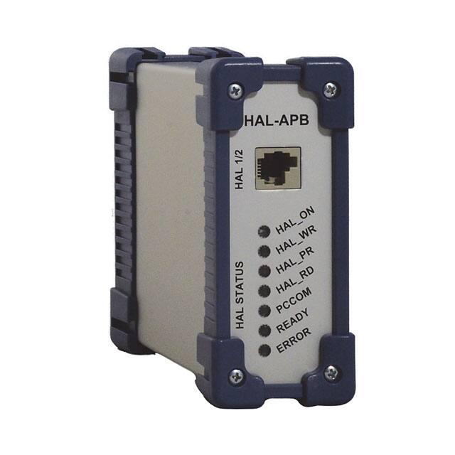
Fig. 1–1:
1.2.
Application Board HAL-APB V1.x
Introduction
The Application Board HAL-APB V1.x (HAL-APB) is an board for programming the
Micronas Hall-effect sensor families with analog and digital output formats. The board
is equipped with a Micronas Flash micro controller CDC 3207G. It provides an application software supporting a command interface for the communication with a PC. This
allows the implementation of specific PC software for engineering purposes or in-line
calibration. The HAL-APB can be ordered with a housing or as a PCB version.
In the case of a housing, an additional extension board with two sockets for the connection of up to two Hall sensors (depending on the sensor type) is supplied.
Two versions of the Application Board HAL-APB are in use: version 1.3 and the
updated version 1.5. Both versions are free to be used in laboratories for engineering
purposes.
Note: For usage in the production, board version 1.5 is mandatory.
6
Oct. 8, 2012; APN000055_003EN
Micronas
�HAL1820, HAL24xy, HAL28xy, HAL36xy, HAL38xy
APPLICATION NOTE
Application Board HAL-APB V1.x
1.2.1.
Supported HAL Sensors
The HAL-APB supports the sensors listed in Table 1–1.
Table 1–1:
Supported sensors
Sensor
Remark
HAL 1820
Linear sensor with analog output
HAL 242x
Linear sensor with analog output
HAL 2810
Linear sensor with LIN 2.0 Interface
HAL 283x
Linear sensor with SENT Interface
HAL 2850
Linear sensor with fast PWM output
HAL 3625
Direct angle sensor with analog output
HAL 3675
Direct angle sensor with PWM output
HAL 385x
2D position sensor with analog output
HAL 387x
2D position sensor with PWM output
Please refer to the corresponding Programming Guides Application Notes for detailed
information on the sensors listed or contact the Application Support Sensors
(support_sensor@micronas.com).
1.2.2.
Sensor-specific PC Software
Micronas GmbH provides easy-to-use PC software (LabView) for each supported sensor.
Micronas
Oct. 8, 2012; APN000055_003EN
7
�HAL1820, HAL24xy, HAL28xy, HAL36xy, HAL38xy
APPLICATION NOTE
Application Board HAL-APB V1.x
1.3.
Board Block Diagram
V_Board
OLED
Extension
(optional)
5V-MCU
USB
5V-PER
5V-ANA
LIN
Module
(optional)
EEPROM
Hall
MCU
RS232
Interface
CDC3207
GND
JTAG
Fig. 1–2:
HAL-APB block diagram
V_Board
TP VDD
Hall device
VDD_Hall Driver
Voltage
VDD
Reference
Switch
Slew
Control
Voltage Level
(Optional)
Control
A/D
Sens
VDD/3
A/D
Sens
VOUT1
VOUT_1
Switch
MCU
Digital
TP8 - IDD
Transceiver
GND
Fig. 1–3:
8
VOUT_2
GND
Detailed view of HAL Interface
Oct. 8, 2012; APN000055_003EN
Micronas
�HAL1820, HAL24xy, HAL28xy, HAL36xy, HAL38xy
APPLICATION NOTE
Application Board HAL-APB V1.x
2. Getting started
2.1.
2.1.1.
First Steps
Check HAL-APB V1.x
– Connect the HAL-APB to the supply voltage.
– Check if the power-on self-test was passed successfully. (ERROR LED is switched
off after power on. Exception: LIN mode)
Board Supply
The HAL-APB requires a stabilized power supply. For this purpose, either when using it
without housing, the connector X2 (DC jack) or the terminal beneath it can be used.
Power-On Self-Test
The HAL-APB firmware provides a power-on self-test. The self-test is started after connecting the board supply. During the self-test, the status LEDs including the Error LED,
will flash.
In case of a detected error, the ERROR LED remains illuminated after the self-test. In
LIN mode the ERROR LED is switched on as long as the Vsupply of the sensor is not
set to 12 V.
2.1.2.
Check Communication with PC and Hall Sensor Connection
Connect a Hall sensor with the HAL-APB.
(a) directly into the socket HAL 1
or
(b) into one of the sockets of the HAL-APB extension board (housing version).
Note: For the first communication check, we recommend using the sensor specific
Programming Environment LabView software provided by Micronas for the specific HAL sensor.
you can also
– set up a Hyperterminal connection (see Section 6 on page 18)
– switch Vdd on using the “vho1” command (see Section 7.2 on page 21).
– try to read out a register (see chapter of the used sensor type).
Micronas
Oct. 8, 2012; APN000055_003EN
9
�HAL1820, HAL24xy, HAL28xy, HAL36xy, HAL38xy
APPLICATION NOTE
Application Board HAL-APB V1.x
3. Board Configuration
3.1.
Jumper Settings
For changing between LIN-Bus and Biphase-M communication, jumpers need to be set
differently. For non-housed (optional) application boards it may be necessary to switch
jumper for USB/RS-232 connection. The following pictures show how to set the jumpers correctly.
+18 VDC
X4 - RS232
(SUB-D-9)
SW X3
USB
JP3 (B)
X2
X4 - RS232
(SUB-D-9)
X3
SW USB
JP3 (B)
+18 VDC
X2
Reset
JP2
JP5
JP1
CDC3207G
Status LEDs
Status LEDs
HAL-APB
Version 1.5
TP8
TP7
TP8
JP6 JP5 JP7 JP4
HAL-APB
Version 1.3
TP7
CDC3207G
JP1
Reset
JP4
HAL1
Status LEDs on housing
Fig. 3–1:
RJ-45
HAL1/2
HAL1
Status LEDs on housing
RJ-45
HAL1/2
Jumper settings HAL-APB V1.x
The default jumper position Pos1 is indicated by black bars in Fig. 3–1.
Note: For board versions higher than v1.3, no manual adjustment is required. The
HAL-APB firmware automatically detects the appropriate protocol to be used for
the Hall sensor.
10
Oct. 8, 2012; APN000055_003EN
Micronas
�HAL1820, HAL24xy, HAL28xy, HAL36xy, HAL38xy
APPLICATION NOTE
Application Board HAL-APB V1.x
Table 3–2:
Jumper settings
Jumper
Setting
Function
JP1
pos1 (default)
debug
pos2
normal operation
V1.5
communication via RS232
open (default)
manual MCU reset during firmware flash
JP2
close
automatic MCU reset during
firmware flash
V1.3
JP3
JP4
JP5
pos1 (default)
normal operation
pos2
reserved
close (default)
USB
open
RS-232
close (default)
VDD_Hall equals GND when
Vsup is switched off
open
VDD_Hall is floating when
Vsup is switched off
V1.5
communication via USB
open (default)
manual MCU reset during firmware flash
close
automatic MCU reset during
firmware flash
V1.3
JP6 (only V1.3)
JP7 (only V1.3)
close (default)
normal operation
open
only for LIN Bus applications
close (default)
normal operation
open
only for LIN Bus applications
open (default)
normal operation
close
only for LIN bus applications
Note: JP7 must not be set in combination with JP4 and JP5 (only V1.3)
Micronas
Oct. 8, 2012; APN000055_003EN
11
�HAL1820, HAL24xy, HAL28xy, HAL36xy, HAL38xy
APPLICATION NOTE
Application Board HAL-APB V1.x
Table 3–3:
12
Board LED description
LED Name
Function
ERROR
On, in case of communication error
READY
On, after power-on of board
PCCOM
On, in case of communication between PC and HALAPB
HAL_RD
Telegram on VOUT
HAL_PR
reserved
HAL_WR
Telegram high level on Hall VDD
HAL_ON
Hall VDD on
Oct. 8, 2012; APN000055_003EN
Micronas
�HAL1820, HAL24xy, HAL28xy, HAL36xy, HAL38xy
APPLICATION NOTE
Application Board HAL-APB V1.x
3.2.
HAL Interface Connector
Depending on the sensor type, up to two sensors can be connected to the board. For
this purpose, a 6-pin connector HAL1/2 is provided. Alternatively, one Hall Sensor can
be inserted in the 3-pin socket HAL beneath the connector HAL1/2 (only available for
boards without housing).
The following pin’s are connected in parallel Pin No. 1(VSUPSensor1) and 4
(VSUPSensor2) and Pin No. 2 (Common Sensor GND) and Pin No. 5 (Common Sensor
GND). The male plug (modular RJ-12, OST (MMJ) coding) corresponding to the fawn
connector HAL1/2 can be ordered from every electronics store. The pinning of the interface is described in Table 3–4.
Table 3–4:
Pinning of the HAL interface HAL1/2
Pin No.
Description
1
Sensor input
VSUP Sensor 1
2
Common Sensor GND
3
Sensor output VOUT/DIO Sensor 1
4
Sensor input
VSUP Sensor 2
5
Common Sensor GND
6
Sensor output VOUT/DIO Sensor 2
Fig. 3–2:
3.3.
Modular connector HAL1/2, front view
Firmware update
The procedure for a firmware update of the HAL-APB V1.x is provided in the Application Note “Firmware Update HAL-APB V1.x”
Micronas
Oct. 8, 2012; APN000055_003EN
13
�HAL1820, HAL24xy, HAL28xy, HAL36xy, HAL38xy
APPLICATION NOTE
Application Board HAL-APB V1.x
4. Specification
4.1.
Recommended Operating Conditions
All voltages are referenced to GND (-VB pin at X1 = GND at X2)
Table 4–5:
Symbol
Board conditions
Parameter
Connector
Limit Values
Unit
Min.
Typ.
Max.
ISUP
Supply Current
X2
-
180
-
mA
VSUP
Supply Voltage
X2
16
18
20
V
CL
Load Capacitance
HAL1/2
-
-
100
nF
4.2.
Test Conditions
Recommended Wiring
We recommend connecting the application to the board using shielded wires.
In order to minimize the risk of electromagnetic disturbances, the cable should be as
short as possible.
Note: Especially in noisy environments beneath power switches, electromagnetic
actuators, and the like, EMI-compliant layout of the wiring is mandatory.
For recommended cable parameters, please refer to Table 4–6.
14
Oct. 8, 2012; APN000055_003EN
Micronas
�HAL1820, HAL24xy, HAL28xy, HAL36xy, HAL38xy
APPLICATION NOTE
Application Board HAL-APB V1.x
4.3.
Maintenance and Calibration
We recommend sending the programmer board back to the supplier for maintenance
and calibration of the voltage levels after one year of operation.
The Hall programmer board must not be maintained or repaired by the customer. In
case of any problems or defects, please contact your supplier.
WARNING: Do not modify any part of the Hall programmer board V 1.x, nor readjust
any trimming potentiometer. Otherwise, the board may be damaged, the
sensor programming may be insufficient, and the reliability of the sensor
reduced.
VDD
Customer Application
GND
Programmer Board V 1.x
VOUT
L
Fig. 4–3:
Table 4–6:
Recommended wiring - schematic sketch
Recommended cable parameters
Symbol
Parameter
Min.
Typ.
Max.
Unit
Conditions
R0
Ohmic Resistance per Wire
1
5
I < 10 mA
C0
Capacitance
80
120
pF
Z
Impedance
50
L
Length
1
m
Micronas
Oct. 8, 2012; APN000055_003EN
15
�HAL1820, HAL24xy, HAL28xy, HAL36xy, HAL38xy
APPLICATION NOTE
Application Board HAL-APB V1.x
4.4.
Characteristics
All voltages are referenced to GND (-VB pin at X1 = GND at X2)
Table 4–7:
Board characteristics
Symbol
Parameter
Connector
Limit Values
Min.
Typ.
Max.
Unit
Test Conditions
ISUP_HAL
Output Load Current
HAL1/2
-
-
40
mA
Supply current per
device
VOUT_HAL
Output Voltage of Hall
Device
HAL1/2
0
-
5
V
Standard configuration
(default)
18
V
LIN configuration only!
0
VSUP_HAL_NORM NORM Level of HAL Supply
Voltage
HAL 1/2
4.9
5
5.1
V
VSUP_HAL_LOW
LOW Level of HAL Supply
Voltage
HAL 1/2
5.8
6.0
6.6
V
VSUP_HAL_HIGH
HIGH Level of HAL Supply
Voltage
HAL 1/2
6.8
7.3
7.8
V
Note: The voltage levels are trimmed by the manufacturer. If any of the levels listed are
found to be outside the specification limits, please contact the manufacturer or
the Application Support Sensors Team.
The RS232 cable should be a standard serial cable. Also called straight cable.
16
Oct. 8, 2012; APN000055_003EN
Micronas
�HAL1820, HAL24xy, HAL28xy, HAL36xy, HAL38xy
APPLICATION NOTE
Application Board HAL-APB V1.x
5. USB Driver Installation
Note: When using the serial cable you do not need to install this drivers. They are only
necessary for connecting the Application Board HAL-APB V1.x via USB cable to
the PC.
5.1.
Installing the USB VCP Drivers
Plug in the Application Board HAL-APB V1.x (Power supply also connected) into a
spare USB port and plug in the power supply.
Windows 7 will automatically search latest driver if the PC is connected to the internet.
If there are problems with the installation follow the application note:
“AN_119_FTDI_Drivers_Installation_Guide_for_Windows7.pdf”
The application note: “AN_104_FTDI_Drivers_Installation_Guide_for_WindowsXP.pdf”
can be used to install the driver on a windows xp system.
The application note can be either found on the Micronas Service Portal
(https://service.micronas.com/workgroups/) or on the FTDI homepage.
Note: Sometimes the installer repeats the whole procedure. If this happens please do
the same as explained above again.
Micronas
Oct. 8, 2012; APN000055_003EN
17
�HAL1820, HAL24xy, HAL28xy, HAL36xy, HAL38xy
APPLICATION NOTE
Application Board HAL-APB V1.x
6. Board Functions
6.1.
Serial Command Interpreter
This board provides a serial command interpreter for the interaction with a PC, connected via USB or RS232.
The serial communication protocol applies a software handshake:
– The PC acts as a master, the HAL-APB V1.x as slave,
– The HAL-APB V1.x responds to each master COMMAND frame with a RESPONSE
frame.
6.1.1.
Serial Interface Configuration
When using a hyperterminal communication please set the following parameters.
Table 6–8:
6.1.2.
parameter settings of serial interface
Parameter
Value
Bits per second
38400
Data bits
8
Parity
Even
Stop bits
1
Flow control
none
Definition of the COMMAND Frame
The command frame is of variable length. There are basically two types of commands:
1. for board configuration
2. for communication with connected Hall device
The command string has to end with (ASCII character 0x0D), optionally with
(ASCII characters 0x0D, 0x0A).
6.1.3.
Definition of the RESPONSE Frame
The response frame consists of 7...10 characters plus 1 finishing
:....
ST is non-zero in case of errors (see Table 6–9)
18
Oct. 8, 2012; APN000055_003EN
Micronas
�HAL1820, HAL24xy, HAL28xy, HAL36xy, HAL38xy
APPLICATION NOTE
Application Board HAL-APB V1.x
The Rx-characters contain the received data depending on the command (see devicedependent command lists in section 9, 10,...).
6.1.4.
Analog Measurements
Its also possible to measure analog voltages, as the HAL_VDD or the HAL_VOUT with
the ADC of the HAL-APB. The HAL_OUT is only correctly measurable when HAL_VDD
equals 5 V.
Example
ftvdl0 (set VDD to 5 V)
ftana1 (measure HAL_VDD)
ftana2 (measure HAL_VOUT)
VDD = DATA / 1024 x 3 x 5V
VOUT = DATA / 1024 x 5V
DATA is measured by ftana command as explained in Table 7–11.
Micronas
Oct. 8, 2012; APN000055_003EN
19
�HAL1820, HAL24xy, HAL28xy, HAL36xy, HAL38xy
APPLICATION NOTE
Application Board HAL-APB V1.x
6.1.5.
Error Codes
Table 6–9:
20
Error codes
STATUS
Error
0
no error
1
acknowledge error
2
2’nd Acknowledge error
3
invalid command for selected
Mode
4
PID in running table cannot be
modified (LIN)
5
LIN communication Error
6
LIN interface connection Error
7
no PWM (at PWM Duty Cycle
read command)
8
reserved
9
reserved
10 (0xA)
reserved
11 (0xB)
reserved
12 (0xC)
reserved
13 (0xD)
data read error
14 (0xE)
invalid command parameter
15 (0xF)
invalid command
Oct. 8, 2012; APN000055_003EN
Micronas
�HAL1820, HAL24xy, HAL28xy, HAL36xy, HAL38xy
APPLICATION NOTE
Application Board HAL-APB V1.x
7. Board Mode Settings
7.1.
Board Operation Modes
In order to meet the different requirements of the various Hall devices, the board can be
run in different operation modes. When a particular device is used, the corresponding
board mode has to be selected first. The mode list can be displayed by sending the
board command “?m”.
Table 7–10: Board modes
Mode
Description
8
HAL 2810 – LIN Mode
9
HAL 283x/50 – Biphase via DIO- Pin
A
HAL 1820 – Biphase via VSUP Pin
HAL 24xy – Biphase via VSUP Pin
HAL 3625 – Biphase via VSUP Pin
HAL 3675 – Biphase via VSUP Pin
HAL 38xy – Biphase via VSUP Pin
C
HAL 24xy – Biphase via OUT - Pin
HAL 3625 – Biphase via OUT - Pin
HAL 3675 – Biphase via OUT - Pin
HAL 38xy – Biphase via OUT - Pin
7.2.
Board Configuration Commands
The board configuration commands shall be used to
– select the board mode
– set/read configuration data like the bit time or firmware version
– control the power supply VDD_HAL of the connected sensor
Table 7–11: Board configuration
Action
Command
Parameter
Remarks
get firmware version
?v
return :[Version]
firmware release version
Example
=> ?v
smA
vho1
vho0
ftana1
ftana2
board status
5 digit Period
5 digit Pulse width
Example
=> pr1 (OP-bit=0)
xxw08C0008
vho1(switching on VDD_HAL)
10.1.2.
Schedule Tables
Different schedule tables allow the use of unconditional frames and diagnostic/configuration frames. It is possible to switch between 4 schedule tables, where tables 1 to 3
handle unconditional frames and table 4 handles configuration frames. The PIDs given
in the table are the default settings in the HAL-APB V1.x firmware schedule table settings. The PIDs of the unconditional frames in the schedule tables 1 to 3 can be
changed in the test terminal.
This can be only done while the corresponding table is not scheduled! The number of
response bytes is set to a fixed value for each frame inside a schedule table. If a PID is
changed accordingly, this length is applied to the new PID. Changed PIDs are lost after
powering off the HAL-APB V1.x. Each schedule table includes only two LIN frames!
The scheduling time between frames is set to 20 ms (fixed).
Note: To apply more user friendly behavior, especially for the saving of special PID
settings, the calling application software should implement the preservation of
the PID settings.
Micronas
Oct. 8, 2012; APN000055_003EN
39
�HAL1820, HAL24xy, HAL28xy, HAL36xy, HAL38xy
APPLICATION NOTE
Application Board HAL-APB V1.x
Table 10–17:Schedule Tables unconditional frames of the HAL-APB V1.x
Table Number
Description
ID_Table_1
Default scheduling table after startup. It comprises a set address to prepare a data access (W/nR=0) and a Read 2 bytes frame. The address
is arbitrary. the default scheduling prevents the sensor from going into
sleep.
Frame1: PID = 0x03 (set address), 3 bytes
Frame2: PID = 0xc4 (Read 2 bytes), 2 bytes
ID_Table_2
This table prepares an address to read from (W/nR=0) and performs a
4 byte read from there.
Frame1: PID = 0x03 (set address), 3 bytes
Frame 2: PID = 0x85, (Read 4 bytes), 4 bytes
ID_Table_3
This table comprises a frame to write a byte to an address (W/nR=1). A
second frame includes only a dummy 4 byte read from this address.
Frame1: PID = 0x03 (set address), 3 bytes
Frame2: PID = 0x85 (Read 4 bytes), 4 bytes
Table 10–18:Schedule table configuration frames of the HAL-APB V1.x
Table Number
Description
ID_Table_4
This table contains configuration frames to schedule.
The two frames are a request (PID60) and a response (PID61) frame.
the data bytes to be used with the request frame can be set by the user.
Frame1: PID60 = 0x3C, 8bytes
Frame2: PID61 =0x7D, 8bytes
10.1.3.
Error Handling
A global error flag is set if a LIN communication error, e.g. a shorted bus or a disconnected slave has been detected. There is no certain fault confinement implemented but
only this global error information. The last error information can be kept alive or reset.
40
Oct. 8, 2012; APN000055_003EN
Micronas
�HAL1820, HAL24xy, HAL28xy, HAL36xy, HAL38xy
APPLICATION NOTE
Application Board HAL-APB V1.x
10.2.
HAL 2810 (LIN2.0) – Board commands
Note: For general board commands see Table 7–11 on page 21
Table 10–19:HAL 2810 commands
Action
Command
Parameter
Remarks
switch schedule table
lsstabN
N = 1...4
N schedule table No.
return value:
board status (see Table 6–
9 on page 20 for details)
:
received data as 8-digit hex
No.
Example
=> lsstab1
lwpa3047
=> :00000000
set address
lwaSTR
= Write Byte
STR =
address as 4-digit hex No.
return value:
data as 2-digit hex No
board status (see Table 6–
9 on page 20 for details)
:
received data as 8-digit hex
No.
Example
=> lwa304711
=> :00000000
send single shot of
schedule table 3
lsos
return value:
:
received data as 8-digit hex
No.
board status (see Table 6–
9 on page 20 for details)
Example
=> lsos
pr1 (OP-bit=0)
pxr002
=> :0FFB2
set base address
pxsbSTR
STR =
base address as 4-digit hex No.
checksum
return value:
board status (see Table 6–9
on page 20 for details)
:
received data as 5-digit hex No.
Example
=> pxsb30006
=> :000000
48
Oct. 8, 2012; APN000055_003EN
Micronas
�HAL1820, HAL24xy, HAL28xy, HAL36xy, HAL38xy
APPLICATION NOTE
Application Board HAL-APB V1.x
Table 11–21:HAL 283x / HAL 2850 commands
Action
Command
Parameter
Remarks
read byte with base
address
pxrbSTR
STR =
address as 2-digit hex No.
return value:
board status (see Table 6–9
on page 20 for details)
returns data from
address to address+1
:
received data as 4-digit hex No.
checksum
Example
=> pxrb00
pxwb00000
xxsb000001d
xxw0837B76
xxr08